
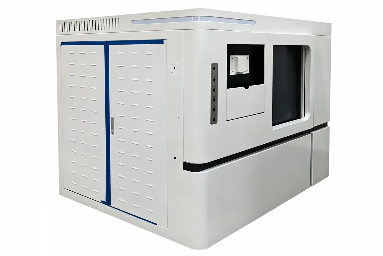
In industrial non-destructive testing (NDT), a compact industrial CT enclosure serves as a multilayer radiation-shielding structure built around a structural steel frame. It combines stainless steel for rigidity and hermetic sealing, an internal lead lining for primary radiation attenuation, labyrinth ventilation ducts for heat dissipation, and lead-glass access doors with safety interlocks. Together, these elements are designed to limit radiation leakage while keeping the enclosure compact.
Stainless-steel and lead composite panels are widely used in NDT-room walls and shielding barriers to protect personnel from X-ray and gamma-ray exposure. Fabricating these enclosures requires strict adherence to radiation-safety standards because even minor defects can affect equipment performance and occupational safety.
This guide breaks down common lead-steel bonding methods, explains why separate lead lining is the industry standard for compact CT systems, outlines core technical challenges, and provides a full-process quality control framework for production.
1. Lead-Steel Bonding Methods and Application Comparison
Five common processes are used to bond lead layers to steel substrates. Each offers a different balance of bond strength, processability, cost, and suitable applications.
Table 1 Lead-Steel Bonding Process Comparison
| Bonding Process | Mechanism | Bond Strength | Formability | Cost | Primary Applications |
| Adhesive Bonding | Lead bonded to steel with epoxy resin via cold or hot pressing | Low (physical adhesion) | Poor; prone to delamination during bending or high-temperature welding | Low | Medical doors, flat wall shielding, simple planar parts with no complex forming |
| Mechanical Locking | Lead and steel interlocked via roller embossing or mechanical piercing | Medium (physical interlock) | Moderate; surface unevenness, risk of delamination on sharp bends | Low-Medium | Lead rubber sheets, simple shielding panels, small basic CT enclosures |
| Cold Roll Bonding | Atomic bonding formed by high-pressure rolling at room temperature | High (metallurgical bond) | Good; compatible with moderate bending and stamping | High | Electronic shielding enclosures, precision instrument components, thin lead layers |
| Hot Roll Bonding | Enhanced atomic diffusion via rolling at elevated temperature | Very high (metallurgical bond) | Excellent; suitable for complex bending, rolling and welding | Very High | Aerospace applications, high-end industrial equipment |
| Explosive Welding | Instant bonding via ultra-high pressure from explosive detonation | Very high (metallurgical bond) | Limited; uneven surface requires post-machining | Very High | Ultra-thick lead composite panels, special dissimilar metal applications (rare for standard CT enclosures) |
Note: Explosive welding is rarely used in standard industrial CT enclosure production due to high cost, long lead times and environmental impact. It is reserved only for special ultra-thick shielding requirements.
2. Advantages of Separate Lead Lining for Stainless Steel CT Enclosures
For high-end compact industrial CT systems, a stainless-steel outer enclosure with a separate internal lead lining remains the predominant design. This approach reflects radiation-shielding requirements, fabrication feasibility, and total cost considerations.
2.1 Shielding Thickness Matching and Design Flexibility
Radiation shielding thickness is calculated based on the maximum voltage (kV) and power of the X-ray source.
-
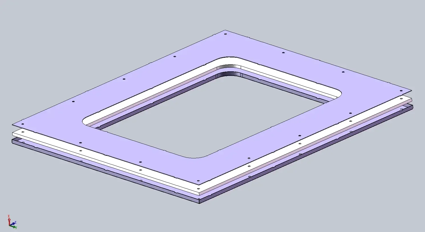
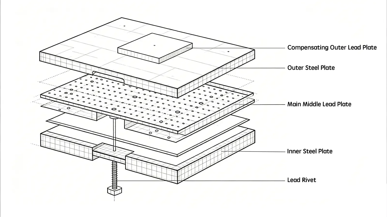
Separate lead lining: Lead sheet thickness can be precisely specified (e.g. 10mm, 15mm, 20mm). Different sections of the enclosure can use different thicknesses to match local shielding demand — for example, 5mm for the top panel and 20mm for the front access panel. This enables targeted, optimized shielding.
-
Pre-bonded composite panel: Composite panels are produced in standard thickness combinations (e.g. 3mm steel + 5mm lead). Matching a non-standard shielding requirement often forces designers to select a thicker-than-needed panel, which increases overall weight and footprint and defeats the purpose of a compact design.
2.2 Fabrication Limitations of Composite Lead-Steel Panels
High-end CT enclosures require complex bends, rounded corners and reinforcing ribs, which create two major risks for pre-bonded panels:
-
Bending delamination: Lead has high ductility but very low tensile strength. During bending, the outer steel layer stretches while the inner lead layer is compressed. Poor process control can cause lead buckling, wrinkling or delamination, creating tiny air gaps that become radiation leakage paths.
-
Welding burn-through: Welding heat melts and vaporizes the lead layer inside composite panels. Lead vapor is toxic and degrades weld quality. Welding composite panels requires removing the lead near the weld before fabrication and restoring the shielding afterward. These extra steps reduce the efficiency advantage of using prefabricated panels.
2.3 Joint Shielding Safety and Redundant Protection
-
Separate Lead Lining (Dual-Layer Protection): In a steel-lead-steel sandwich structure, lead panels are installed after the steel enclosure is welded. Lead joints can be offset from steel welds. Even if a steel weld has minor imperfections, the offset lead layer provides a second line of defense, creating redundant shielding.
-
Pre-Bonded Composite (Single-Point Failure Risk): The lead layer is continuous with the steel panel, and welding is performed after panel assembly. If welding disrupts lead layer continuity, radiation can penetrate directly at the joint.
2.4 Material Cost and Supply Stability Analysis
-
Inventory cost: Pre-bonded composite panels are custom materials with long lead times and high unit cost. Manufacturers producing multiple CT models (225 kV to 450 kV and above) would need to stock many thickness combinations, creating a significant inventory burden.
-
Standard material availability: Stainless steel sheet and pure lead sheet are standard industrial commodities with transparent pricing and ready supply. Lead sheet can be ordered in the required thickness and cut to size for each order, supporting flexible production schedules.
2.5 Internal Cleanliness and Structural Maintainability
High-precision CT systems (especially for semiconductor inspection) require very high internal cleanliness, often with polished stainless steel interiors. Lead surfaces oxidize and produce toxic lead dust over time.
-
With separate lead lining, a thin inner stainless steel liner is installed after lead placement, fully encapsulating lead within the steel-lead-steel sandwich structure.
-
If pre-bonded panels are used as the inner lining, they leave the lead surface exposed; if they are placed on the outside, they provide no shielding benefit. Adding an inner stainless steel liner to composite panels replicates the complexity of the separate lining approach with no added benefit.
2.6 Structural Strength and Load Distribution
-
Load-Bearing Structure: Core CT components, including the X-ray source, detector, and precision rotary stage, are heavy. The outer stainless-steel frame carries the full structural load.
-
Composite panel limitations: The lead layer in composite panels contributes no structural strength and only adds dead weight. With separate lead lining, engineers can design reinforcing ribs exactly where needed to support lead weight, rather than distributing dead weight uniformly across the entire structure.
3. Technical Challenges of Lead-Lined CT Enclosure Fabrication
Securing soft, oxidizable lead sheet inside a rigid stainless steel enclosure while maintaining reliable radiation shielding presents several key engineering challenges.
3.1 Seam Treatment and Radiation Leakage Prevention
X-rays follow line-of-sight paths and penetrate any gap in the shielding layer.
-
Panel joints: Lead sheets must be joined with lap joints, not butt joints, with a minimum overlap of 20mm to prevent radiation penetration through the seam.
-
Corner treatment: Internal right-angle corners are high-risk points. Lead sheet can crack or gap at sharp bends. Custom cast lead corners or specialized folding procedures are required for continuous shielding.
-
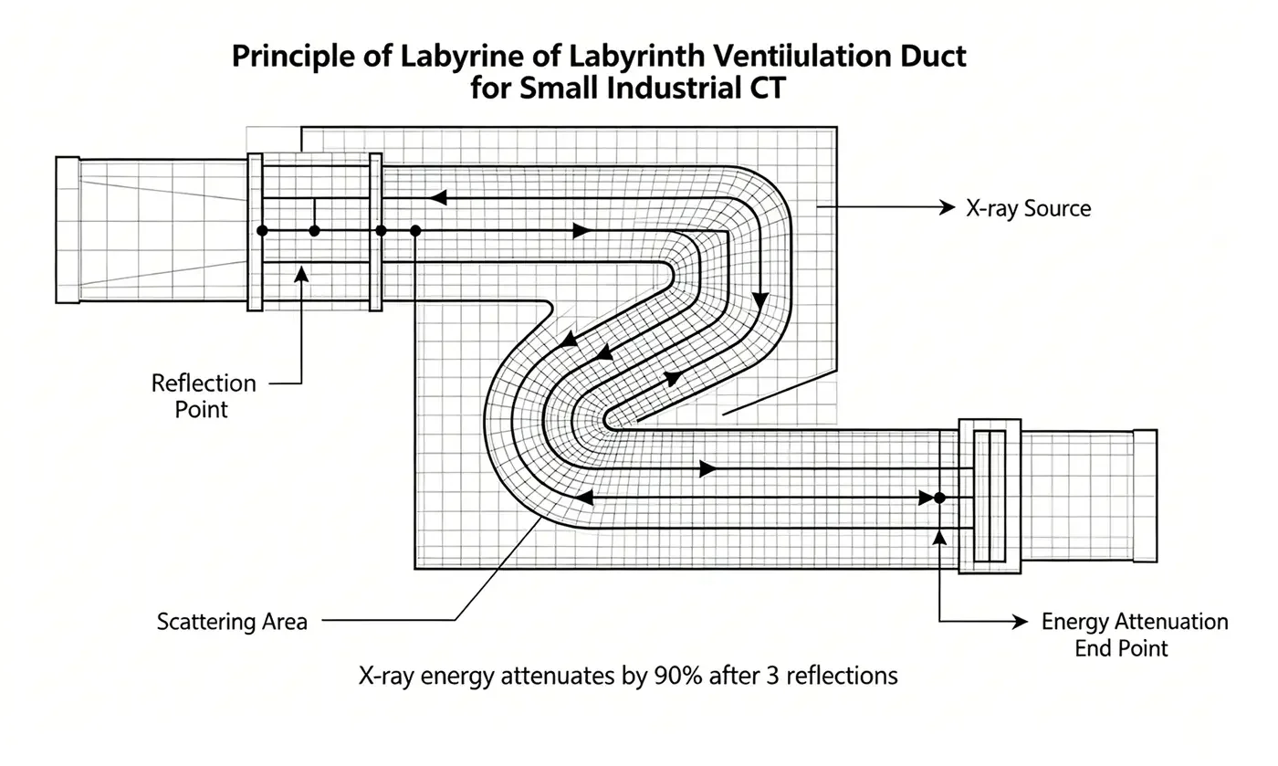
Labyrinth seal design: Openings for part access, viewing windows or ventilation cannot be simple straight holes. They require S-shaped labyrinth structures to attenuate radiation through multiple reflections to safe levels.
3.2 Lead Panel Fixation and Structural Reinforcement
Lead has a density of approximately 11.34 g/cm³ and a Mohs hardness of only 1.5.
-
Sagging risk: In large CT systems with 20–50mm thick lead lining, the self-weight of lead is substantial. Over time, lead can slip or sag on vertical steel walls, creating gaps at the top.
- Solution: Design dedicated retaining slots, cleats or mechanical fasteners to secure lead panels. The stainless steel frame must include reinforcing ribs to support the total lead weight.
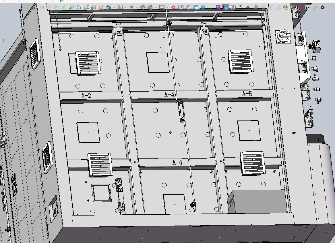
- Load isolation: Lead cannot bear structural loads. The stainless-steel frame must carry all equipment weight; no equipment should rest directly on the lead lining.
3.3 Lead Oxidation and Internal Contamination Control
-
Lead oxidizes in air, forming lead oxide that produces toxic dust.
-
To prevent lead dust from contaminating test parts (especially precision components), inner lead surfaces are covered with a thin stainless steel liner, aluminum sheet or epoxy coating for full encapsulation.
3.4 Cable and Utility Penetration Shielding
Internal systems require power cables, data cables (Ethernet and fiber-optic), and compressed-air lines to pass through the shielding enclosure.
-
Core challenge: Cable penetrations must not break shielding layer continuity.
-
Solution: Use purpose-built shielded connectors, or seal penetrations thoroughly with lead putty or lead rubber after cable routing.
3.5 Door Structure and Hinge Sealing Design
CT enclosures are fitted with heavy lead-lined access doors.
- Door gap sealing: Door edges are the most common radiation leakage points. Designs use tongue-and-groove edge profiles, or flexible lead rubber gaskets compressed between door and frame.
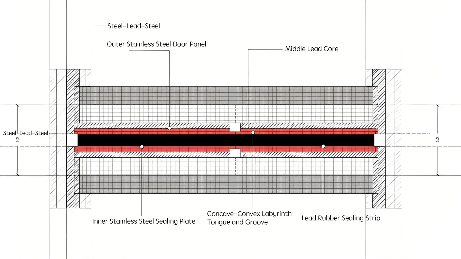
- Hinge durability: Lead-lined doors are very heavy. Hinges must have extremely high load capacity and maintain dimensional accuracy after long-term use. Even micrometer-scale frame deformation can cause radiation leakage to exceed limits.
3.6 Thermal Dissipation and Vent Shielding Design
X-ray tubes generate significant heat during operation, and detector arrays also produce heat during scanning.
-
Core conflict: Thicker shielding improves radiation safety but reduces heat dissipation.
-
Solution: Use precision internal ductwork with heat-exchanger fins routed through labyrinth openings in the shielding wall, or use a water-cooling system to remove heat. Both approaches require careful shielding around each feedthrough.
4. Full-Process Quality Control for Industrial CT Enclosures
For compact industrial CT enclosures, quality assurance and testing are critical to safety. Compact design means shielding layers are close to internal components, making post-assembly leakage repair extremely difficult and costly.
4.1 In-Process Quality Assurance
The focus at this stage is prevention. Once the enclosure is fully sealed, internal shielding defects are nearly impossible to repair.
Incoming Quality Control (IQC)
-
Lead sheet inspection
-
Purity: Verify material test certificates (MTC) to confirm minimum 99.9% lead purity. Impure lead with antimony or other additives has reduced ductility and poor formability.
-
Thickness tolerance: Measure thickness at multiple points with a micrometer. Design typically includes a safety margin (e.g. 12mm specified for a 10mm calculated requirement), and actual thickness must not fall below the design minimum.
-
-
Stainless steel sheet inspection
- Check surface flatness and freedom from deep scratches. Surface depressions reduce contact quality with the lead layer and can create hidden gaps.
Shielding Installation Process Control
This is the highest-risk stage and requires oversight by a dedicated quality inspector.
-
Lap joint inspection: Verify all lead joints use lap joints, not butt joints. Confirm minimum 20mm overlap, and check for gaps with feeler gauges.
-
Fixation verification: Confirm lead panels are secured with mechanical fasteners and retaining slots. Vertical walls must have positive support structures to prevent long-term sagging and delamination.
-
Corner & penetration inspection: Verify internal corners use cast lead pieces or approved folding methods, with no breaks in lead continuity. Confirm cable and pipe penetrations have properly sized lead openings with a bell-mouth profile for full shielding overlap.
Labyrinth Structure Line-of-Sight Test
Access openings and ventilation ducts on compact CT systems use labyrinth designs.
-
Candlelight test (line-of-sight check): Place a bright light source inside the enclosure. Inspect all external openings from the outside.
-
Pass criteria: No direct light visible from any external opening. If light can pass through, radiation can also leak. This is a simple, low-cost validation of labyrinth effectiveness.
Door & Hinge Pre-Assembly Test
-
Verify lead rubber gaskets are properly fitted, with compression within design specification (typically 30–50% compression).
-
Simulate door closing before lead installation and measure gap width to confirm compliance with maximum allowable gap for shielding calculation.
4.2 Final Acceptance Testing
After full enclosure assembly and welding, comprehensive physical and radiation testing is mandatory.
Helium Mass Spectrometer Leak Test (for vacuum CT systems)
For high-end vacuum CT systems where the enclosure also serves as the vacuum chamber:
-
Seal all ports, charge with helium, and scan all welds with a helium mass spectrometer.
-
Purpose: Verify the stainless steel enclosure is free of pinhole leaks. Primarily for vacuum integrity, but also validates weld density.
Surface Flatness & Visual Inspection
-
Tap test: Tap enclosure surfaces lightly with a rubber mallet.
-
Acceptable: Dull, uniform sound across the surface.
-
Defect indication: A hollow, drum-like sound indicates delamination between lead and steel, which can cause vibration or long-term failure and requires rework.
-
-
Visual check: Confirm that external surfaces are free of weld spatter and deformation and that the brushed or polished finish is consistent.
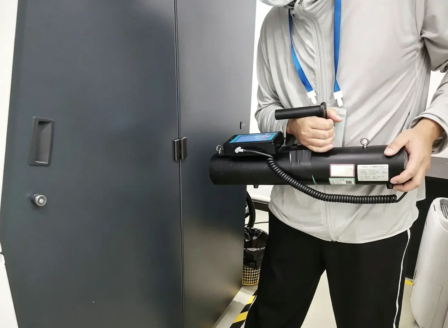
Radiation Leakage Survey (Core Acceptance Test)
This is the final acceptance criterion for delivery. Testing must use calibrated radiation survey meters (ionization chamber type).
-
Test conditions
-
Use an empty-chamber test as the standard procedure; some standards also require a representative test object to account for scattered radiation.
-
Operate the X-ray source at its maximum kV and mA settings.
-
Rotate the stage through 360° to cover all angles.
-
-
Survey procedure
-
Hold the detector close to the enclosure surface, typically 5 or 10 cm away, as specified by the applicable GBZ 130 or ISO 13950 requirement.
-
Focus on high-risk spots: welds, door gaps, viewing windows, cable ports, ventilation openings, caster mounting holes.
-
-
Acceptance criteria
-
General limit: ≤ 1 μSv/h measured 5 cm from the enclosure surface; the article identifies this as the exemption level used in many national regulations.
-
Operator-position limit: ≤ 2.5 μSv/h at the normal operating position.
-
Safety Interlock Function Verification
While this is an electrical function, it must be verified together with enclosure mechanical design:
-
Door interlock: Confirm X-ray emission stops immediately when the door is opened.
-
Emergency stop: Confirm X-ray is cut off and all motion stops when emergency stop is activated.
-
Safety relay test: Simulate a short circuit in the safety circuit and confirm that the system enters a fault state and prevents start-up.
Mechanical Strength & Durability Testing
-
Door cycle test: Perform hundreds of opening-and-closing cycles on the heavy lead-lined door, and check for hinge sag and gasket wear.
-
Vibration test: Simulate transport vibration to check for loose internal lead panels or rattling.
5. Core Quality Principles for Reliable Radiation Shielding
Fabrication of high-end compact CT enclosures follows three non-negotiable quality principles:
-
No line-of-sight gaps: All openings must pass the line-of-sight light test with zero direct light penetration.
-
Radiation leakage within regulatory limits: Full surface radiation survey must meet all applicable national and international safety standards.
-
No delamination between lead and steel: Lead lining must be fully secured with no hollow or detached areas that could fail over time.
For compact systems, ventilation openings are the most common radiation leakage point due to the conflict between heat dissipation and shielding, and require extra attention during QA.
Conclusion
Reliable compact industrial CT enclosures depend on the proper separation of lead and steel, precision TIG welding, and full-penetration hermetic seams. Mature fabrication processes offset steel welds from lead-shielding joints and maintain strict cleanliness and material-embrittlement controls, creating a robust barrier that balances structural strength, radiation safety, and a compact footprint.