
The geometric accuracy of welded joints is a core factor that determines the mechanical performance and service life of metal structures. Among common welding defects, misalignment—called mismatch in AWS/ASME terminology and hi-lo in shop-floor usage—is a typical but difficult-to-detect defect.
While it may appear as a minor cosmetic issue, misalignment significantly alters joint stress distribution, induces fatigue cracking and accelerates corrosion. It is a leading cause of early failure in pressure vessels, process pipelines and structural steel projects.
This guide provides a comprehensive overview of weld misalignment, including its standard definition, measurement methods, failure mechanisms, international acceptance limits, and full-process quality controls. It is intended as a practical reference for welding-procedure development, field fabrication, and quality inspection.
1. Definition and Standard Measurement Methods of Weld Misalignment
1.1 Core Definition
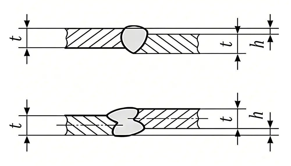
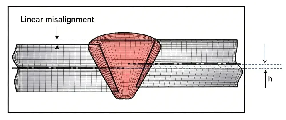
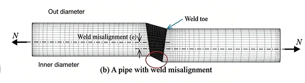
Weld misalignment is the longitudinal height offset between two base metal surfaces at the joint centerline. It must be distinguished from the transverse groove gap. The misalignment value is the maximum height difference between the base-metal surfaces on either side of the joint, excluding weld reinforcement.
-
Standard term per ISO 6520-1:2017: Misalignment, defect code 507
-
Term used in AWS/ASME systems: Mismatch
-
Common shop-floor term: Hi-lo, one of the most frequent dimensional deviations encountered during fit-up
1.2 Standard Measurement Procedure
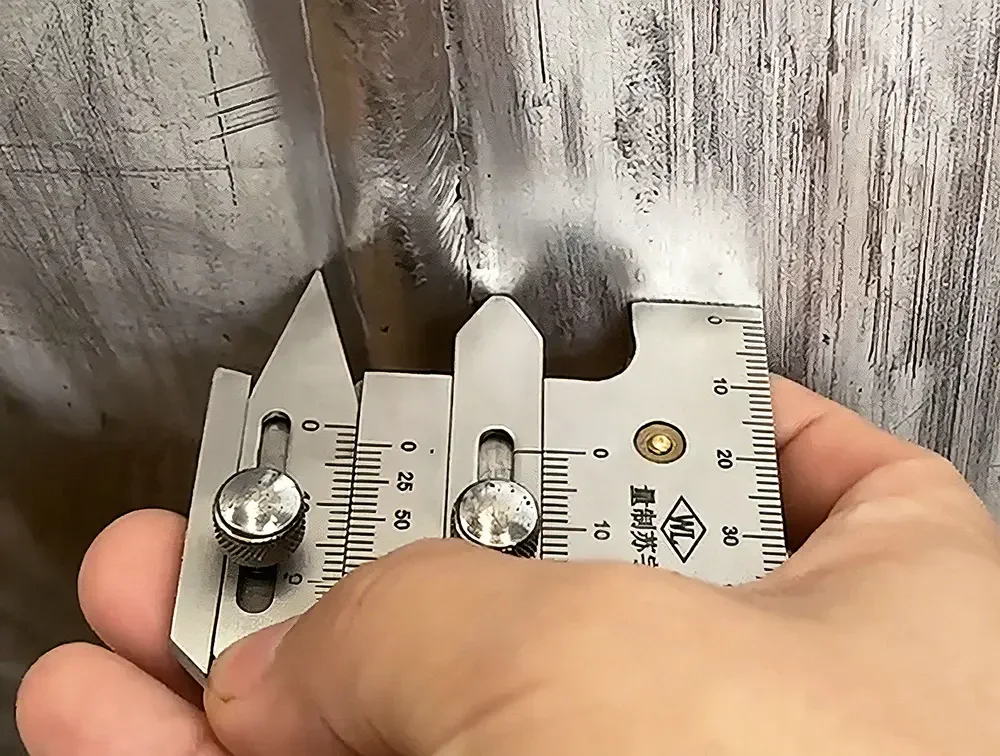
Accurate measurement is the foundation of misalignment control. Different joint types require standardized sampling and operating procedures:
-
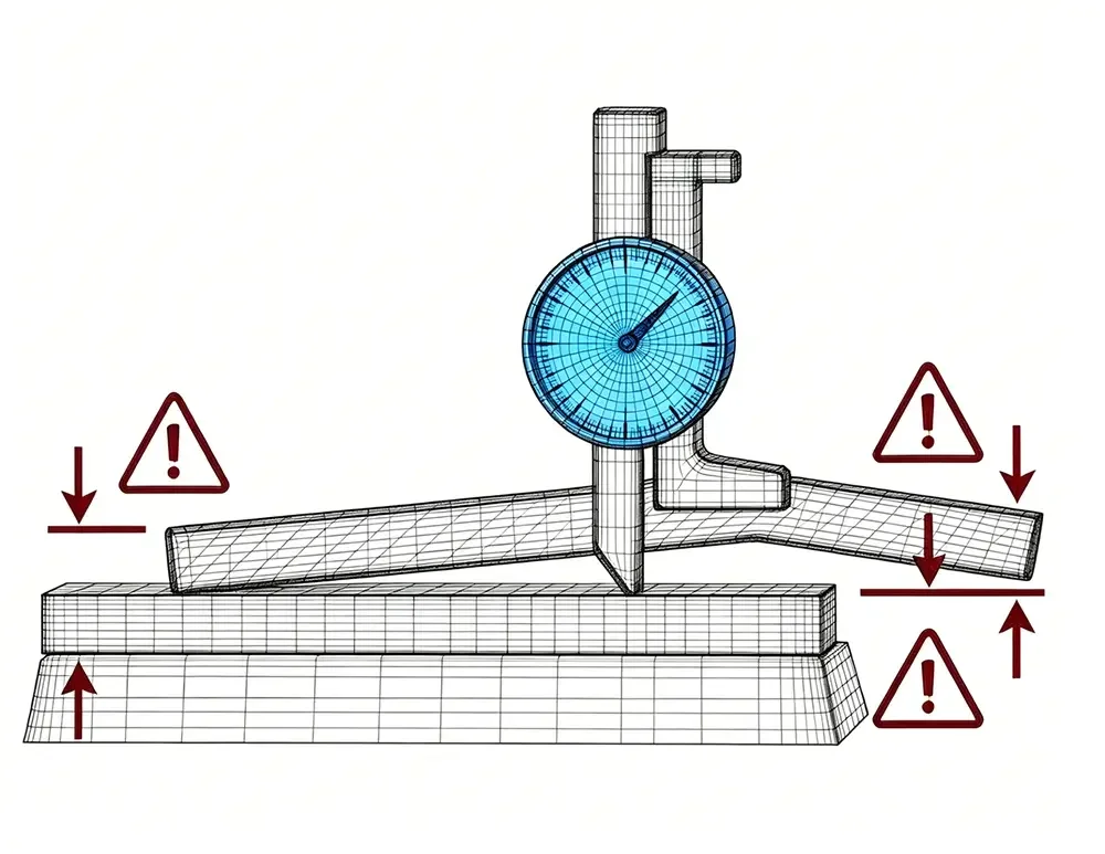
Datum alignment: Use a dedicated hi-lo gauge or high-precision vernier caliper. Press the datum face firmly against the higher base metal surface, slide the measuring probe to lightly contact the lower surface and take the reading. Do not apply excessive force that may deform base material and skew results.
-
Point sampling: For flat plate butt welds, take one measurement every 300–500mm along the weld length. For circumferential pipe or cylinder joints, measure at a minimum of four equally spaced positions (0°, 90°, 180°, 270°). Use the maximum reading as the final acceptance value.
-
Two-measurement rule: Take the first measurement after tack welding and before final welding so that fit-up can be adjusted promptly. Take a second measurement after welding for final acceptance and quality documentation.
1.3 Common Misconceptions
-
❌ “It is just a small step and does not affect performance”: Misalignment is a structural defect, not an appearance issue. For a 10mm thick plate, 1mm misalignment equals 10% of plate thickness, which exceeds acceptance limits of most mainstream standards.
-
❌ “Weld reinforcement can cover misalignment”: Weld reinforcement consists only of deposited weld metal. The step and structural discontinuity in the base metal remain, so the source of the stress concentration is not removed.
-
❌ “Groove gap and misalignment are the same problem”: The groove gap is the transverse opening at the joint, whereas misalignment is the longitudinal height offset. Both are fit-up defects but have entirely different causes and correction methods.
2. How Misalignment Degrades Welded Joint Performance
Welded-structure design assumes a uniform stress distribution. The section discontinuity created by misalignment disrupts load paths and reduces mechanical strength, fatigue life, and corrosion resistance.
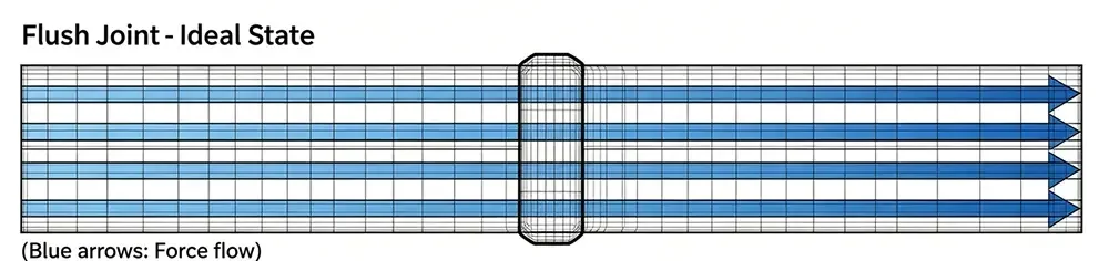
2.1 Deterioration of Mechanical Properties
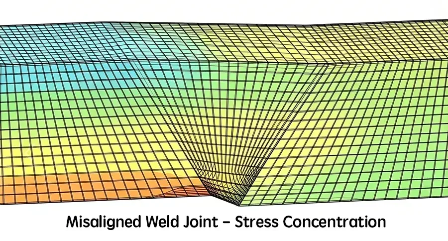
Stress Concentration Effect In an ideal flush joint, force lines transfer smoothly. The step created by misalignment causes sharp deflection of force lines, forming a high stress concentration zone at the step root.
Stress Concentration Factor, Kt
-
When misalignment reaches 10% of plate thickness, the stress concentration factor Kt reaches 1.6–1.9, meaning local stress is 60%–90% higher than the nominal design value. This area becomes a primary site for brittle fracture and crack initiation.
-
When misalignment reaches 20% of plate thickness, Kt rises to 2.3–2.8. Even under normal design load, the actual local tensile stress can reach nearly 3 times the design value.
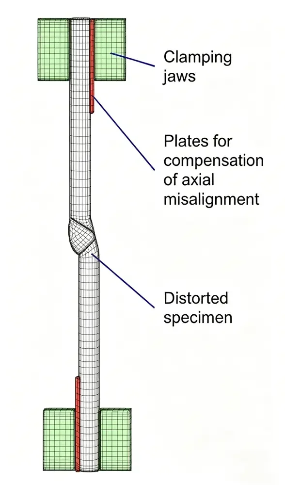
Section eccentricity effect
-
Additional bending stress: Misalignment changes the load mode of the joint. The original axial tensile load becomes a combined tensile-and-bending stress state, adding secondary bending stress. The actual load-bearing capacity of the joint drops far below theoretical design values, and sudden fracture may occur under extreme working conditions.
-
Reduced effective bearing area: Misalignment reduces the effective mating cross-section of the base metal at the joint, decreasing the component’s load-bearing area and directly lowers the ultimate bearing capacity of the joint.
2.2 Reduced Fatigue Life
For welded structures under cyclic loads (hoisting machinery, bridges, power pipelines), the impact of misalignment on fatigue life is particularly pronounced.
Misalignment directly lowers the fatigue strength class (FAT value) of the joint. Fatigue life is inversely proportional to the cube of the stress range. Industry research indicates that when the stress-concentration factor reaches 2.0, joint fatigue life may fall to one-eighth of the design value. Components designed for 10 years of service may develop fatigue cracks at misaligned joints and fail within 1–2 years.
Reference calculation parameters:
-
Plate thickness t = 20mm
-
Measured misalignment c = 2 mm
-
Design stress range Δσnom = 100 MPa
-
Weld detail: transverse butt weld, original FAT = 90M
2.3 Accelerated Corrosion Failure
In corrosive environments—including chemical-processing plants, coastal or outdoor locations, and high-temperature, high-pressure service—misalignment can significantly accelerate localized corrosion:
-
Crevice Corrosion: The narrow gap formed by misalignment traps corrosive media and contaminants. Limited oxygen diffusion inside the gap creates an oxygen concentration cell, accelerating local corrosion. Stainless steel is particularly prone to pitting corrosion at these sites, which can gradually penetrate the base material.
-
Stress Corrosion Cracking (SCC): The coupling effect between stress concentration zones and corrosive media greatly accelerates crack propagation. In chloride environments, acidic conditions or high-temperature scenarios, This failure mode is difficult to detect and can progress rapidly, often reaching a critical state before it is discovered.
3. Acceptance Limits Under Major International Welding Standards
Welding codes across different industries and regions specify quantitative requirements for misalignment, which form the core basis for quality acceptance. The limits below apply to conventional plate thicknesses ranging from 1 to 50 mm.
Table 1 Weld Misalignment Acceptance Limits by Standard
Core Principles for Standard Application
-
Confirm the applicable code system before project startup; do not set limits based on experience alone.
-
Proportional limits become stricter as thickness decreases. Uniform fixed values shall not be applied across all thicknesses.
-
All measurement data and correction records must be archived for quality traceability and third-party inspection.
4. Full-Process Control & Rectification Methods
The core principle of misalignment management is prevention first, correction second. Post-weld correction is difficult and carries high risk; the vast majority of deviations should be eliminated before fit-up and welding.
4.1 Cutting & Pre-Assembly: Source Control
The root cause of many misalignment issues lies not in fit-up, but in upstream cutting and incoming material quality:
-
Cutting quality inspection: Maintain strict control of plate and pipe edge straightness. Base material with wavy edges, camber or other deformations must be straightened before moving to the next process. For high-precision projects, Laser cutting is preferred for high-precision projects to maintain accurate edge geometry.
-
Base material thickness verification: Measure the thickness of materials used in the same joint at multiple points to avoid misalignment caused by cumulative thickness tolerances.
-
Unequal thickness plate pretreatment: When joining plates of different thicknesses, machine a 1:3 transition slope in advance per code requirements before fit-up, to avoid post-weld grinding rework.
-
Groove surface cleaning: Fully remove oil, rust, oxide scale and other contaminants from the weld zone, to prevent uneven deformation during welding that may indirectly cause misalignment.
4.2 Fit-Up & Tack Welding: Core Control
Fit-up is the most critical process for misalignment control. Standardized fit-up procedures eliminate most misalignment issues.
-
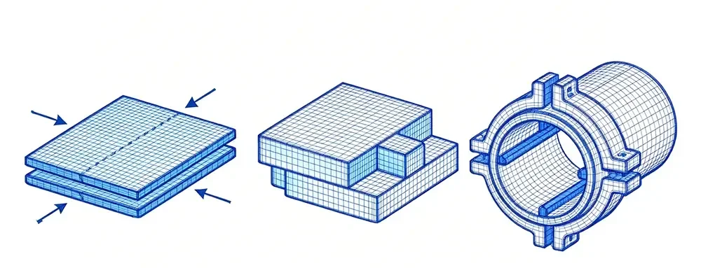
Dedicated fit-up tooling: Use positioning blocks, quick clamps, and fit-up jigs that match the component geometry. Use modular tooling for long welds and large components; use internal and external line-up clamps for pipes and cylinders to ensure joint concentricity.
-
Align first, tack second: Place base material on a horizontal tooling platform, verify alignment with a straight edge or laser level, and confirm flush surfaces and matching centerlines before applying tack welds.
-
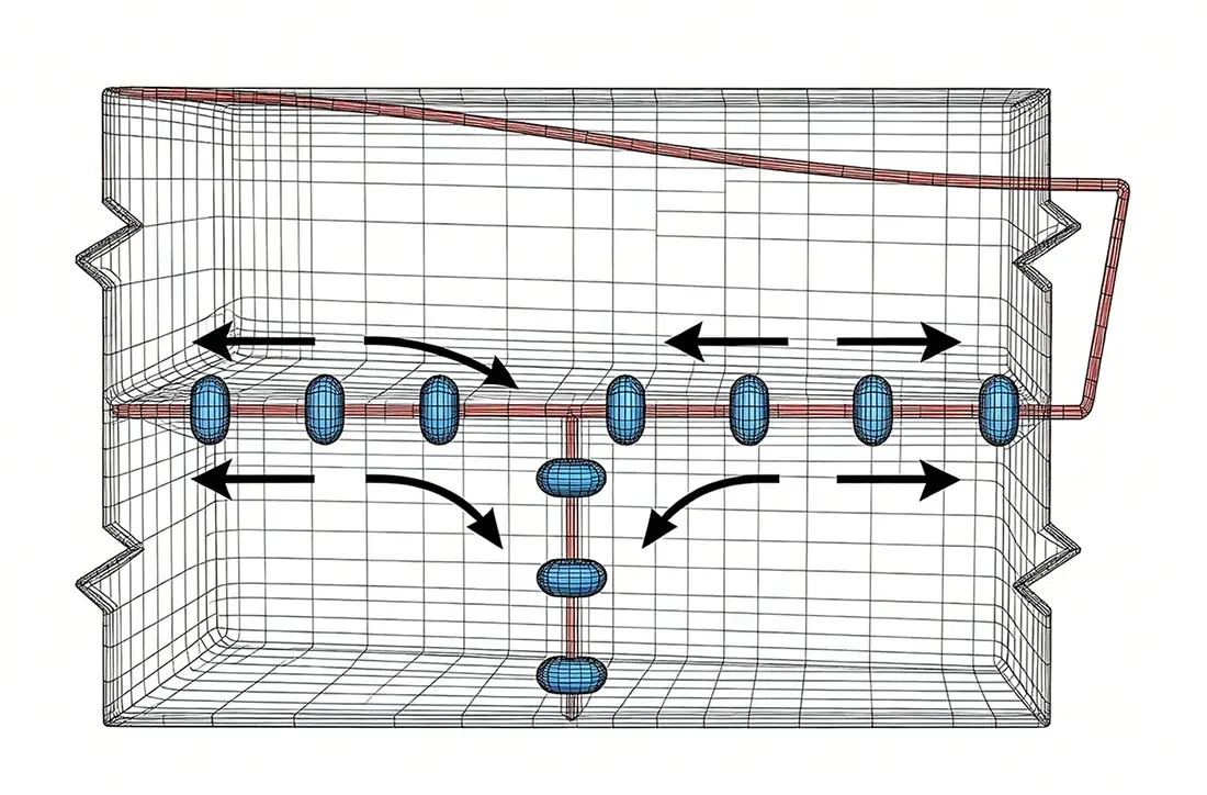
Standardized tack welding procedure: Use segmented symmetrical tack welding. For flat plate butt welds, place tack welds every 300–500mm, distributed symmetrically from center to ends. Tack welds shall not be oversized, but must have sufficient strength to prevent cracking and shifting during final welding.
-
Re-inspection after tack welding: Re-measure misalignment after tack welding is complete. Minor deviation within 2mm may be fine-tuned with tooling; deviation exceeding 2mm requires removal of tack welds and re-fit-up. Welding with out-of-tolerance deviation is prohibited.
4.3 Welding Process: Deformation & Displacement Control
Thermal expansion and contraction from welding heat input can pull base material out of alignment. Even qualified fit-up can develop misalignment with improper welding procedures.
-
Low heat input processes: For thin plates and thin-walled components, pulsed MIG or TIG welding is preferred. Select appropriate parameters to control heat input and minimize distortion.
-
Symmetrical & backstep welding: For long welds, use an alternating sequence—front/back and left/right—to balance heat input. For welds longer than 1 meter, use backstep welding to reduce overall shrinkage deformation.
-
Backing pad support: For thin plate butt joints, ceramic or copper backing can be installed. This ensures consistent back-side weld formation and prevents base material shift caused by weld collapse.
4.4 Misalignment Rectification: Priority & Application Scope
When misalignment occurs, select correction methods by priority. Random surfacing to compensate for misalignment is prohibited.
Table 2 Weld Misalignment Rectification Methods by Priority
4.5 Mandatory 1:3 Taper Transition Requirement
Per ASME B31.3 and GB/T 150 requirements: when plate thickness difference exceeds code limits, a smooth transition taper must be machined with a minimum slope of 1:3.
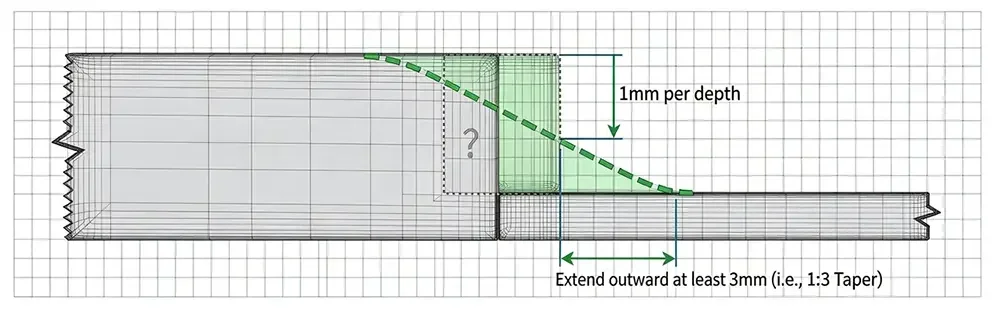
This geometric reshaping redirects internal force flow, eliminates critical stress concentration at sharp corners, and converts abrupt section discontinuity into a gradual, smooth transition.
4.6 Quality Inspection & Traceability
-
Post-weld final inspection: Re-measure misalignment at code-specified points. For corrected joints, perform penetrant testing or magnetic particle testing if required to check for surface cracks.
-
Recordkeeping: Record measurement data, correction actions, document identifiers, applicable standards, and measurement-point details in the quality file to maintain traceability.
-
Continuous improvement: Track misalignment occurrence frequency across different structures and processes, optimize tooling design and operating procedures, and gradually reduce defect rates.
5. Practical Guidelines for Misalignment Management
-
Standardize process documentation: Incorporate misalignment limits directly into the Welding Procedure Specification. Define specific allowable values for different thicknesses, joint forms and applicable standards, to avoid on-site judgment based on experience and ensure consistent process execution.
-
Strengthen Operators’ Quality Awareness: Many frontline operators treat misalignment as an appearance issue and do not recognize its impact on structural safety. Conduct regular technical training with failure case studies to use failure case studies to instill the principle that “misalignment creates stress concentrations” and discourage informal “close enough” practices.
-
Prioritize process control: Once misalignment occurs, post-weld correction is costly and often ineffective. The most efficient and reliable approach is to move control upstream to cutting and fit-up and reduce deviations at the source through better tooling and process optimization.
Conclusion
Weld misalignment is one of the most underestimated defects in welding. It can be difficult to detect, yet it has a significant effect on the mechanical performance, fatigue life, and corrosion resistance of welded structures and can contribute to premature failure.
From material preparation and fit-up positioning to welding execution and quality inspection, standardized execution at every step eliminates hidden structural safety risks. Mastering acceptance limits across different codes and implementing full-process control is the core foundation for ensuring long-term, reliable service of welded structures.